

From Multiple Power Sources to Coordinated Operation: Engineering Synchronization and Load Sharing for DGs and Mains
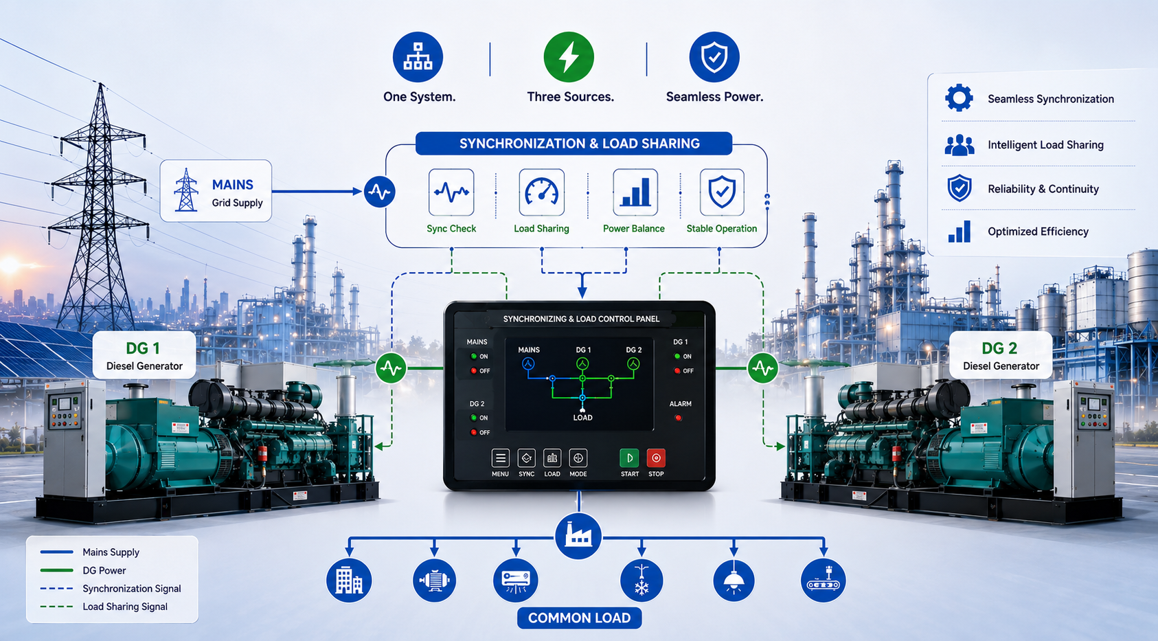
The client facility had three available power sources: the utility supply and two diesel generators. The challenge was not the absence of generation capacity. The challenge was coordinating these sources so that they could operate reliably according to changing power requirements.
When the facility’s power requirement changes, the system must determine whether one generator is sufficient or whether additional generation is required. When a second generator needs to be connected to an energized electrical system, the sources must be synchronized before they can operate together. When the available generation capacity exceeds the immediate requirement, the system must follow an appropriate operating strategy. When the mains supply changes, the transition between sources must be controlled.
The engineering problem, therefore, is not simply: How do we start a diesel generator when the mains fails? It is: How should multiple available power sources be coordinated so that the facility receives reliable and controlled power under changing operating conditions?
This was the central challenge addressed in a recently commissioned system involving:
- Two diesel generators
- Mains/grid supply
- Automatic synchronization
- Load-sharing functionality
- Selec PLC
- Selec HMI
The project demonstrates an important transition in power-system engineering.
A diesel generator is traditionally considered a backup source. But when a facility operates multiple DGs alongside the mains supply, the system can no longer be treated as a collection of independent sources. It needs to be treated as a coordinated power system.
The client had power sources. The challenge was making them work together.
The facility already had the basic ingredients of a resilient power system. There was a mains supply. There were two diesel generators. Together, these sources provided the facility with multiple options for maintaining power availability.
However, the operating challenge was created by the interaction between these sources.
The system needed to be capable of managing different operating conditions.
When the mains supply was available, the facility needed to operate according to its defined mains-power strategy. When the mains supply was unavailable, the DG system needed to provide the required power. When the load demand exceeded what one generator could practically support, additional generation capacity could be required. When both DGs needed to operate together, they could not simply be connected to the same electrical system without ensuring that the required synchronization conditions were satisfied.
The problem was therefore not a lack of generation capacity. The problem was coordinating the generation capacity that was already available.
A facility can have several power sources and still face operational challenges if those sources are not coordinated through a suitable control strategy.
The system must be able to answer questions such as:
- Which sources are available?
- Which source is currently supplying the load?
- Is one DG sufficient for the current operating condition?
- Is additional generation required?
- Can the second DG be connected?
- Are the electrical conditions suitable for synchronization?
- How should the available load be distributed?
- How should the system respond when the mains supply changes?
These are not questions that can be answered by a simple ON/OFF arrangement. They require the power system to be measured, evaluated and controlled.
The engagement began with understanding the operating requirement
The solution could not begin with selecting a PLC. The first requirement was to understand how the power system needed to operate.
A synchronization and load-sharing system is not a standard solution that can be applied identically to every facility. The control philosophy depends on the actual configuration of the power sources, the expected operating conditions, the load requirement and the way the facility wants the system to behave.
The discussion therefore had to move beyond the question: Which controller should be installed? The more important question was: What should the complete power system do when operating conditions change?
That meant understanding the interaction between:
- Mains supply
- DG-1
- DG-2
- Connected load
- Breakers and switching
- Synchronization requirements
- Operator intervention
- Automatic control
The purpose of the engagement was to convert the client’s operational requirement into a defined control philosophy. Instead of treating each DG as an isolated backup unit, the system had to be considered as a group of available power sources.
This changed the nature of the solution. The requirement was no longer simply to automate generator starting. It was to coordinate multiple sources. That coordination required the system to understand the operating condition, determine the appropriate action and execute the required sequence.
The requirement became clear: automatic coordination of multiple sources
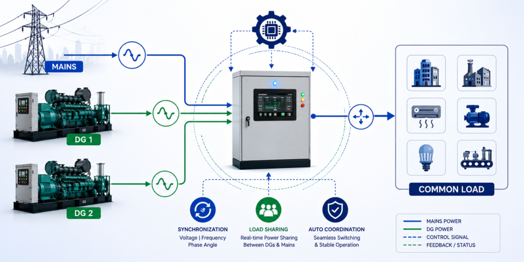
After understanding the operating requirement, the need for a coordinated system became clear. The solution had to bring together three available power sources:
- Mains/grid supply
- Diesel Generator 1
- Diesel Generator 2
The system needed to support automatic synchronization and load sharing between the available generation sources and the mains supply according to the defined operating requirements.
The agreed control objective was therefore to create a system capable of:
- Monitoring the status of the available sources.
- Coordinating the operation of the two DGs.
- Managing synchronization where required.
- Enabling coordinated load sharing.
- Supporting controlled source transitions.
- Providing an operator interface for visibility and operation.
A conventional backup system may follow a fixed sequence:
Mains fails → DG starts → Load transfers
A coordinated system must be capable of handling a wider range of conditions:
Source condition changes → System evaluates the condition → Appropriate source strategy is selected → Required sequence is executed → Result is monitored
This requires a more structured automation architecture.
The mutually agreed solution: a central control layer for the power system
The agreed solution was based on a PLC and HMI architecture using Selec automation hardware.
The Selec PLC provided the central control layer. The controller was responsible for receiving information from the system, evaluating the available conditions and executing the programmed operating logic. The HMI provided the operator interface.
The overall architecture brought together:
- Two DG sources
- Mains/grid source
- Source-status information
- Electrical operating conditions
- Synchronization logic
- Load-sharing functionality
- Control sequences
- Operator visibility
The PLC was therefore selected as part of a broader control architecture rather than as an isolated component.
The controller needed to receive information regarding the operating condition of the available sources. This could include source availability, generator status, electrical parameters, breaker status and other relevant signals required by the control philosophy.
It then needed to evaluate whether the available conditions satisfied the requirements for the next action.
For example:
- Is the source available?
- Is the generator operating?
- Are synchronization conditions suitable?
- Is the second generator required?
- Is a connection permitted?
- Is a transition required?
Based on the defined logic, the system could then initiate the required operating sequence. This could involve:
- Generator start or stop commands
- Synchronization sequences
- Breaker control
- Load-sharing operation
- Source transitions
The system also needed to confirm the resulting operating condition. A command is not the same as a completed action. A start command does not necessarily mean that the generator is running. A breaker command does not necessarily mean that the breaker has reached the intended position. A reliable control system therefore depends on feedback.
The HMI complemented this architecture by providing the operator with a consolidated view of the system. Instead of relying on multiple independent indications, the operator could obtain visibility into the operating state of the coordinated power system.
The HMI could provide information such as:
- Mains status
- DG-1 status
- DG-2 status
- Breaker status
- Operating mode
- Synchronization status
- Load-sharing status
- Alarms and system conditions
The result was a control architecture designed to make multiple sources operate as a coordinated system.
Synchronization was the key to bringing sources together
The most important technical challenge emerged when multiple sources needed to operate together.
A generator can be running correctly and still not be ready to connect to an energized electrical system. Before a source is connected to an energized bus, its electrical conditions must be suitably aligned with the existing system.
The synchronization process therefore involves evaluating the relationship between the incoming source and the energized electrical system. Depending on the system architecture and control scheme, this typically involves parameters such as:
- Voltage
- Frequency
- Phase sequence
- Phase angle
The system cannot simply assume that a running generator is ready for connection. The generator may be mechanically operating correctly, producing voltage and running at the required speed. But the electrical conditions must still be evaluated before the connection is permitted.
Generator available → Generator running → Electrical conditions evaluated → Synchronization conditions confirmed → Connection permitted → Source connected
This is why synchronization is fundamentally different from simply switching a generator ON. The system must establish whether the two electrical sources are suitably aligned before the connection is made.
The PLC provides the control logic required to coordinate this sequence. The system evaluates the available information, applies the defined conditions and controls the sequence accordingly. This reduces dependence on manual intervention and allows the synchronization process to be executed consistently.
Load sharing allowed the available generation capacity to be coordinated
Synchronization allows multiple sources to operate together. The next challenge is determining how the available generation capacity should be used.
The facility had two DGs. Depending on the operating condition, one generator may be sufficient, while at other times additional generation capacity may be required. The system therefore needed to coordinate the operation of both DGs.
The purpose of load sharing is to allow the available generation capacity to be coordinated rather than treating each generator as an independent unit.
The operating objective may include:
- Distributing the connected load between available generators.
- Avoiding unnecessary dependence on one generator.
- Bringing additional generation capacity into operation when required.
- Supporting stable operation when multiple generators are operating.
- Providing greater flexibility as the load condition changes.
It is important to distinguish between load sharing and an automatic guarantee of energy savings. Load sharing by itself does not mean that fuel consumption will always decrease. The actual efficiency of a generator system depends on several factors, including:
- Generator capacity
- Actual load demand
- Generator efficiency
- Operating duration
- Loading conditions
- Control strategy
The value of coordinated load sharing is that it allows the system to respond to the actual operating requirement. The facility is not restricted to treating every operating condition identically. Instead, the available generation capacity can be managed through a defined control strategy.
That is the value of automation: it converts a complex operating requirement into a repeatable sequence of decisions.
Implementation required more than installing the hardware
Once the control philosophy was defined, the next stage was implementation. This involved translating the agreed operating requirements into a working automation system.
The PLC and HMI had to become part of the electrical and generator-control architecture. The system needed to receive the relevant information, process it through the defined logic and execute the required actions.
The implementation therefore involved the integration of:
- Source-status information
- Generator operating conditions
- Electrical conditions
- Synchronization logic
- Load-sharing logic
- Breaker operation
- Operator interface
The HMI also needed to present the system in a way that was understandable to the operator. The operator should be able to see the operating condition of the system rather than having to interpret a collection of disconnected signals.
This is particularly important in a system involving multiple sources. The complexity of the electrical system should not be transferred to the operator. The control architecture should help simplify the operator’s understanding of the system.
The implementation phase therefore had two objectives:
- Make the control system perform the required functions.
- Make the operating condition visible to the people responsible for the facility.
Commissioning was the first real test of the solution
A control system can appear correct in a design document. It can also appear correct during isolated testing. But the real test begins when multiple power sources must operate under actual conditions.
Commissioning therefore required the system to be evaluated as an integrated power system. The important question was not simply: Does the PLC execute the program?
The more important question was: Does the complete system behave as expected when the operating conditions change?
The integrated system was evaluated for the interaction between the mains supply, both DG sets and the control logic. The commissioning process focused on:
- Correct source recognition
- Appropriate control responses
- Synchronization functionality
- Coordinated generator operation
- Load-sharing behaviour
- Controlled source transitions
- Operator visibility through the HMI
The system was successfully commissioned for operation involving two DGs and mains supply. The reported outcome was stable operation, reliable performance and smooth source transitions under real operating conditions.
This was the first important validation of the solution. The system was not merely demonstrated as a theoretical concept; the control architecture was brought into operation in the environment for which it had been designed.
From commissioning to operational stability
Successful commissioning marks the beginning of operation. It does not represent the end of the engineering process.
Once the system moves into regular operation, the focus shifts from proving that the synchronization and load-sharing functions work to ensuring that the system continues to deliver the expected operating behaviour under real conditions.
The system now has to operate through actual changes in:
- Power availability
- Load demand
- Generator operation
- Source transitions
The expectations are straightforward:
- Sources should be coordinated.
- Transitions should be controlled.
- Load should be distributed according to the defined strategy.
- The system should remain stable.
- The operator should have visibility into the operating condition.
The reported outcome of the project was stable operation, reliable performance and customer satisfaction. This reflects an important principle in automation engineering: the value of a system is ultimately determined not by the number of features included in its design, but by how effectively it performs the required function in the operating environment.
As the system becomes part of the facility’s regular operating infrastructure, the emphasis naturally shifts from commissioning activities such as testing, verification and troubleshooting towards reliability, repeatability, controlled transitions, operator confidence and stable source coordination.
The control architecture provides a defined method for managing the two DGs and mains supply. It does not eliminate the need for engineering supervision, but it reduces dependence on manual intervention for repetitive control decisions and creates a more consistent operating strategy.
The next opportunity is to verify the operating behaviour
Once the control system is operating, the next question is whether the actual system behaviour matches the expected behaviour.
This requires measurement and monitoring. A control system may know that a generator is running, but broader monitoring can help answer:
- How long did it run?
- What was the load profile?
- How frequently did it operate?
- How often did the system transition between sources?
- How was the load distributed?
- Were there repeated alarms?
- Were there unexpected operating conditions?
This is where the distinction between control and intelligence becomes important.
Control answers: What should the system do now? Monitoring answers: What has the system been doing? Analysis then helps answer: What does this behaviour tell us?
For example, a facility may discover that:
- A second generator is being called into operation frequently.
- One generator consistently carries a larger share of the load.
- Source transitions occur more often than expected.
- Certain operating conditions repeatedly trigger alarms.
These observations may lead to further engineering decisions involving:
- Load distribution
- Generator operating strategy
- Maintenance requirements
- Capacity planning
- Electrical system behaviour
The control system therefore becomes the foundation for further operational improvement.
The broader lesson from the project
The project illustrates a fundamental principle of industrial automation: the objective is not to automate an isolated component. The objective is to improve the operation of the complete system.
A generator, PLC, HMI and breaker are all individual components. Their real value emerges when they are integrated around an actual operating requirement.
In this case, the requirement was to coordinate:
- Mains supply
- Two diesel generators
- Synchronization
- Load sharing
- Source transitions
- Operator visibility
The solution was therefore designed around the behaviour of the complete power system.
This is why the engineering process matters:
Understand the system → Identify the problem → Define the operating requirement → Develop the control strategy → Implement the solution → Commission the system → Verify the operating behaviour → Improve where required
This is very different from starting with a product and trying to find a problem for it to solve.
The evolution from backup power to power-system intelligence
The traditional DG system is designed around a simple requirement: keep the facility running when mains power is unavailable. That requirement remains important.
However, facilities with multiple power sources increasingly need to understand how those sources should operate together.
They need to consider:
- How multiple sources should operate together.
- How available generation should be coordinated.
- How source transitions should be managed.
- How the system should respond to changing demand.
- How the operating performance should be verified.
Synchronization and load sharing are important steps in this evolution. They allow multiple sources to function as part of a coordinated system.
PLC-based control provides the decision-making layer. The HMI provides visibility. Electrical measurement provides the information required for decisions. Monitoring and analysis provide the basis for improvement.
Measure → Understand → Control → Verify → Improve
The system first needs information. That information needs to be understood in the context of the operating requirement. The required action must then be executed through the control system. The outcome needs to be verified. Finally, the accumulated experience and data can be used to improve future operation.
Reliable power is ultimately about coordinated decisions
The successful commissioning of a two-DG and mains synchronization and load-sharing system demonstrates that reliable power is not created simply by adding more generation capacity.
The facility already had multiple sources. The engineering challenge was to make those sources operate together in a coordinated manner.
The solution emerged through a defined process:
- The operating context was understood.
- The problem was identified as a source-coordination challenge.
- The control requirement was defined.
- A PLC and HMI-based architecture was agreed.
- Synchronization and load-sharing functionality were implemented.
- The system was commissioned under real operating conditions.
- The result was stable operation, reliable performance and smooth source transitions.
The larger lesson is that power reliability is a system property. It depends not only on the reliability of individual components, but also on the quality of the decisions that coordinate those components.
A facility with multiple power sources does not automatically have a resilient power system. It has the potential for resilience. That potential is realised when the sources are properly measured, protected, controlled, coordinated and continuously evaluated.
From Power Source Coordination to Better Operational Decisions
The next step for facilities operating multiple DGs and mains supply is to look beyond the question of whether the sources can operate together.
The more important questions are:
- Are the sources being used according to the actual load requirement?
- Are source transitions occurring as expected?
- Is the generation capacity being coordinated effectively?
- Are the operating conditions stable?
- Are recurring abnormalities visible?
- Is the available data being used to improve future decisions?
This is where automation and monitoring come together. The objective is not to add technology simply because it is available. The objective is to understand the operating system and identify where better visibility, control or coordination can create measurable value.
At Intelliware, we approach such requirements from the system perspective. The starting point is not a product. It is the operating problem.
We look at the available power sources, the existing control architecture, the electrical conditions, the load requirement and the desired operating behaviour.
From there, the solution may involve a combination of:
- Electrical measurement
- Source monitoring
- PLC-based control
- Synchronization
- Load sharing
- HMI-based visibility
- Energy monitoring
- Operational analysis
The right architecture depends on the facility. But the engineering approach remains consistent: understand the operating condition first, then build the control and monitoring solution around the actual requirement.
If your facility operates multiple DGs, mains supply or other parallel power sources and requires better coordination, controlled transitions or visibility into the system’s operating behaviour, the first step is to review how the system operates today—how sources are measured, how transitions are controlled and where manual intervention is still required.
That assessment provides the basis for determining whether synchronization, load sharing, source automation or additional monitoring can improve the way the power system operates.
Because the path to a more reliable power system does not begin with simply adding another controller. It begins with understanding the system that needs to be controlled.
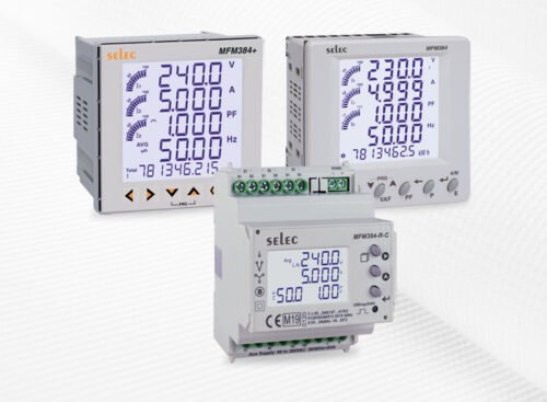 Digital Multifunction Meter